Arduino
Commander un relais suite à la détection d'un mouvement dans l'obscurité.
Publié le 25/11/2018
ATTENTION, dans cette publication nous manipulons du 220V ce qui peut être mortel !!! Les risques sont réels ! Vous le faites sous votre responsabilité.
Débranchez avant toute manipulation, rendez impossible l'accès aux contacts (boîte étanche)...
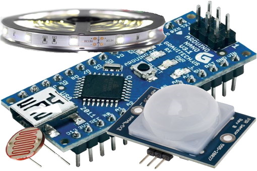
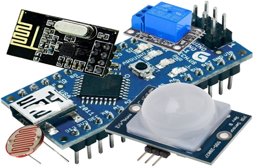
Liste des composants nécessaires pour la réalisation du circuit :
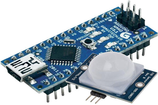
- Arduino nano1
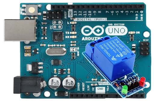
- Relais1
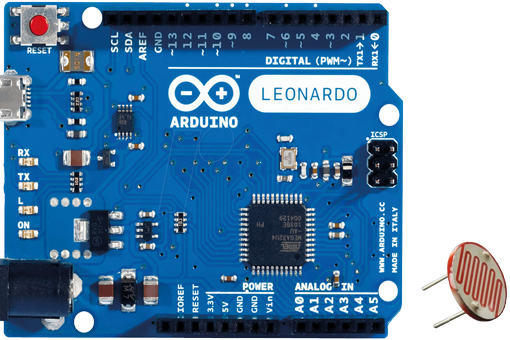
- Photo-résistance1
- Résistance 10 k-Ohms1
- Détecteur PIR1
Schéma du montage électronique :

Pour les amateurs d'impression 3D, j'ai fait quelques templates qui permettent d'imprimer divers boitiers pouvant accueillir les divers composants utilisés dans mes tutoriels.
- Pour un composant PIR, vous trouverez le boitier à imprimer ici.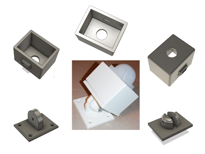
Il faut compter environ 4h pour imprimer les composants de ce boitier.
- Pour un relais, vous trouverez le boitier à imprimer ici.
Il faut compter environ 2h pour imprimer les composants de ce boitier.
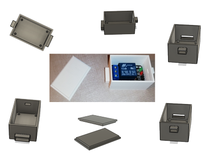
L'ensemble des impressions 3D a été réalisé sur une imprimante Creality3D Ender-3 pro avec les réglages standards suivants: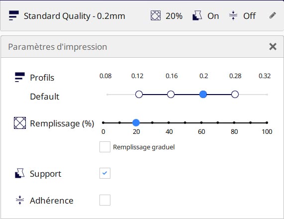
Pour les personnes possédant Fritzing, voici le schéma électronique.
Voici le code à télécharger dans votre Arduino:
#define pinPIR      2                    // Pin pour le capteur PIR
#define pinRelais   5                    // Pin pour le relais
#define pinPhotoresistance   0           // Pin pour la photoresistance. The cell and 10K pulldown are connected to a0

void setup()
{
	Serial.println(F("************"));
	Serial.println(F("Arduino Nano"));
	Serial.println(F("************"));
	Serial.println(F(""));

	Serial.println(F("\nInitialisation..."));
	Serial.println(F(""));

	Serial.println(F("Connection du capteur PIR"));
	Serial.println(F(""));

	Serial.println(F("************************"));
	Serial.println(F("          3.3v  5v     *"));
	Serial.println(F("*     GND DATA  VCC    *"));
	Serial.println(F("*      .    .    .     *"));
	Serial.println(F("*                      *"));
	Serial.println(F("*                      *"));
	Serial.println(F("*      O         O     *"));
	Serial.println(F("*    Timer     Sensi   *"));
	Serial.println(F("************************"));
	Serial.println(F(""));

	Serial.print(F("On calibre le capteur PIR (7s)"));

	for(int i = 0; i < 7; i++)
	{
		Serial.print(F("."));
		delay(1000);
	}

	Serial.println(F(""));

	pinMode(pinRelais, OUTPUT);
	digitalWrite(pinRelais, LOW);

	pinMode(pinPIR, INPUT_PULLUP);
}

//*****************************************************************************************//
//                                      MAIN LOOP
//*****************************************************************************************//
void loop()
{
	int val = digitalRead(pinPIR);

	// Mouvement detecte
	if (val == HIGH)
	{
		// Lecture de la photo-resistance
		int ii_photocellReading = ReadLuminosity();
		if (ii_photocellReading < 200)
		{
		  Serial.println(F("On doit allumer la lumiere\r\n"));
		  digitalWrite(pinRelais, HIGH);
		}
		else
		{
		  Serial.println(F("On ne doit pas allumer la lumiere\r\n"));
		  digitalWrite(pinRelais, LOW);
		}
	}
	else
		digitalWrite(pinRelais, LOW);
}

int ReadLuminosity()
{
    int ii_photocellReading = analogRead(pinPhotoresistance);
    Serial.print("Analog reading = ");
    Serial.print(ii_photocellReading);

    if (ii_photocellReading < 10) {
      Serial.println(" - Noir");
    } else if (ii_photocellReading < 100) {
      Serial.println(" - Pénombre");
    } else if (ii_photocellReading < 200) {
      Serial.println(" - Sombre");
    } else if (ii_photocellReading < 500) {
      Serial.println(" - Lumiere");
    } else if (ii_photocellReading < 800) {
      Serial.println(" - Lumineux");
    } else {
      Serial.println(" - Tres lumineux");
    }
}
